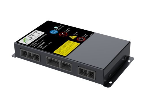
X-BCU MASTER Controller
Please contact us for Sales.
In the X-Series BMS, the X-BCU provides total system monitoring and control, while the X-MCUP controllers manage battery cells directly. The X-BCU master controller supports connectivity for up to 20 X-MCUP controllers.
Originally developed for use in electric buses, the X-Series BMS’s patent pending expandable design is best suited for medium to high voltage lithium-ion battery packs and is highly configurable for many different applications. Features include isolated CAN bus communications, support for up to 240 cells, and automatic configuration of X-MCUP modules upon connection to the X-BCU master.
To learn more about this BMS master controller, see our X-Series overview or the X-BCU data sheet.
- Automatic X-MCUP module detection and configuration
- Comprehensive system high voltage monitoring
- Dynamic State of Charge (SOC) and State of Health (SOH) algorithms adapt to aging cells
- Over 80 fault conditions monitored at all times
- Regulated power output for X-MCUP controllers
- Ground fault detection
- Automotive grade components
- Extremely low power dissipation
- Configurable alarm levels
- IP55 protection rating
- 3 Isolated CAN bus channels
- Configurable inputs and outputs
- Cell lifetime data recorded in controller memory
- Integrated BMS Link software for your laptop or PC allows you to:
- Monitor and export data
- Control your battery pack directly
- Diagnose problems
|
Parameter |
Value |
|
Supply Voltage |
9–32 V |
|
Number of X-MCUP modules |
1–20 |
|
Battery Voltage |
up to 1000 V |
|
X-MCUP Power Supply |
|
|
Output Voltage |
24 V |
|
Output Current |
3.7 A |
|
Current Protection |
3.8 A |
|
Battery Voltage Monitoring |
|
|
Range (full) |
0-1000 V |
|
Accuracy |
0.1 % |
|
Current Sensor |
|
|
Automotive dual-range Hall effect sensor |
|
|
Communications |
|
|
Isolated CAN Bus |
1 |
|
Isolated CAN Bus (protocol configurable) |
2 |
|
I/O |
|
|
High-Power Driver (1 A) |
5 |
|
Digital Input |
5 |
|
Digital Output (750 mA) |
1 |
|
Parameter |
Value |
|
Supply Voltage |
9–32 V |
|
Number of Cells |
4–48 |
|
Battery Voltage |
up to 220 V |
|
Cell Voltage Monitoring and Hardware Interlock |
|
|
Measurement Resolution |
1.5 mV |
|
Measurement Gain Error |
±0.12 % |
|
Range |
0–5 V |
|
Measurement Period |
50 ms |
|
Cell Temperature Monitoring |
|
|
Cell Temperature Measurement Resolution |
0.1 °C |
|
Cell Temperature Measurement Accuracy |
1.0 % |
|
Cell Temperature Measurement Range |
-100–100 °C |
|
Cell Balancing |
|
|
Passive Balancing Current |
250–300 mA |
|
Current Sensor |
|
|
Automotive dual-range Hall effect sensor |
|
|
Communications |
|
|
Isolated CAN Bus |
1 |
|
CAN Bus (diagnostic) |
1 |
|
Isolated RS-232 |
1 |
|
I/O |
|
|
High-Power Driver (1 A) |
2 |
|
Digital Input/Output (750 mA) |
4 |
|
Digital Input/Output (750 mA) OR |
2 |
